.
.
Displaying Temperature/Humidity on a I2C LCD
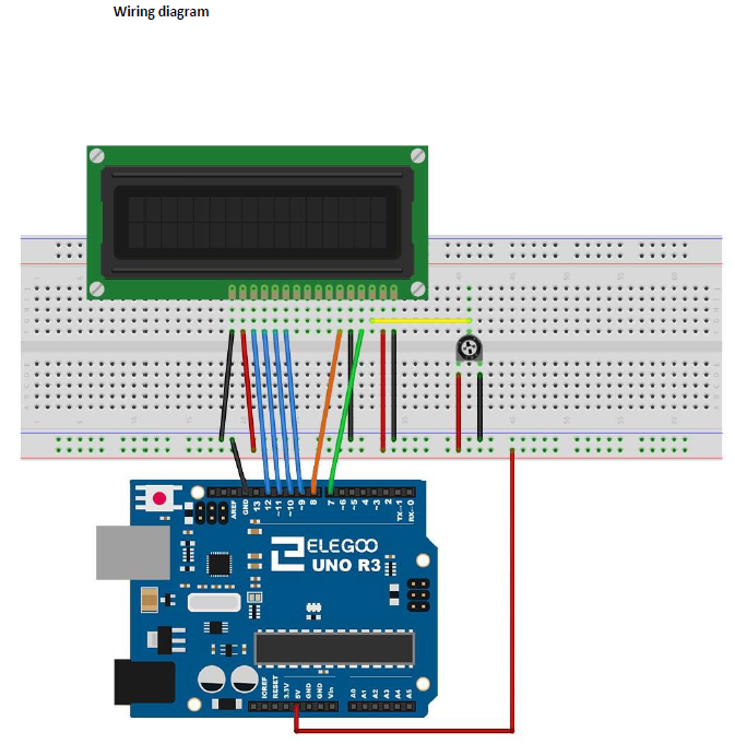
We were already playing around, as seen on my tutorials below, with the Temperature/Humidity sensors DHT11, DHT22 and LCD1602, without I2C possibility. There were a lot of cables to connect, we will try out this time to use a LCD with I2C bus connection as it uses ONLY 4 wires to connect. It’s a perfect project for newbies in coding as they will see the measured values directly on the LCD screen, the success and happy factor is guaranteed!
Related tutorials:
- https://gustmees.wordpress.com/2018/01/22/first-steps-with-the-arduino-uno-r3-maker-makered-coding-super-starter-kit-uno-r3-project-lcd-and-sensors-project/
- Check out the above tutorial to find out about the cabling, this one with I2C is much less cabling (wiring)! 😉
- First Steps with the NodeMCU ESP8266 | Maker, MakerED, Coding | Text on I2C-LCD1602 Display written over Web-Page
- First Steps with the Arduino-UNO R3 and NANO | Maker, MakerED, Coding | Scrolling text with I2C-LCD1602
- …
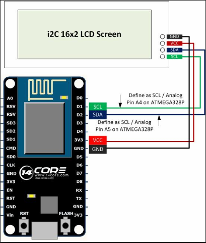
Let us have first a look on the wiring (cabling) which is actually very easy, have a look below please:
.
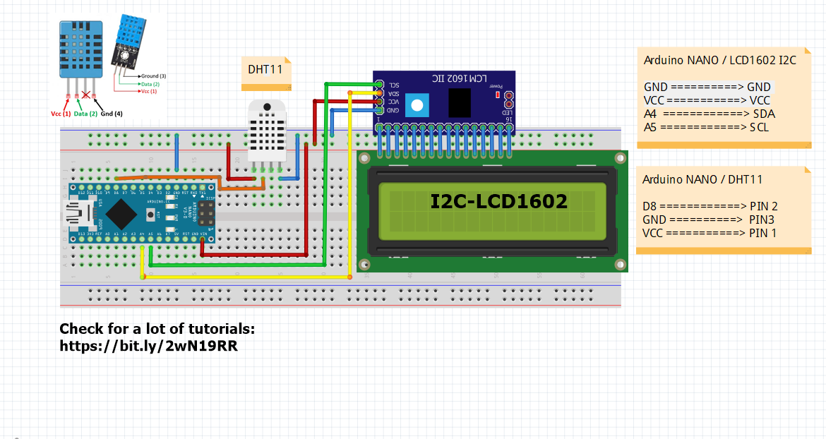
====> Click image, please, to enlarge.
The wiring (cabling) will take about +/- 5-10 minutes depending on your own rhythm… Let us have a look on the coding now: we will use exactly the same code (Sketch) as in our first tutorial here, which we will change just a bit to fit for I2C LCD1602 display:
Copy&Paste the code from above tutorial where it is marked “I also made an example where I display the results on a LCD. Here’s the source code of that example:” and paste it into the Arduino IDE. Connect the Arduino NANO with your computer now. Open the Arduino IDE and choose the board “Arduino NANO”, see screenshot below, please:

Click image, please, to enlarge.
.
Next step, on the same Arduino IDE select the Processor:
.

Click image, please, to enlarge.
.
TIP: when the LED on the Arduino NANO is lightning GREEN it is an original NANO and you must choose “Atmega328P”; if the LED is lightning RED, it is a clone and you must choose “Atmega328P (Old Bootloader)”.
.
NOW it is about time to adapt the code (Sketch) to an I2C-LCD1602 display, let us have a look on the Sketch (the original):
.

Click image, please, to enlarge.
.
As we can see in line 10: the library is meant for a normal LCD display, it needs to get changed for a “I2C LCD Library”.
In line 15: the same it shows the wiring pins for a normal LCD display, it needs to get changed for a “I2C LCD” display.
In line19: It is BETTER to add as well the I2C-Address, mostly “0x27” OR “0x3F”.
That is NOT much to change, we will see in the screenshot below the How-To:
.

Click image please, to enlarge.
.
By enlarging (click on the image) you will see by comparing where the changes are. I commented in the lines the WHY… Try it out to change it yourselves or just download the Sketch (Code) here below who is working:
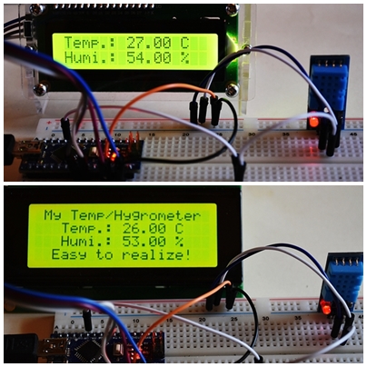
Copy&Paste this code into a NEW Sketch on the Arduino IDE and upload now the code to the Arduino NANO (or Arduino UNO) and enjoy it! 😉 Here below a photo of the working sketch:
.

.
And in case of that you have a I2C LCD with 20×4 configuration it works also, check photo below please:
.

.
As you can see the two first lines from 4 possible lines are only used, that is normal as the Sketch (Code) is actually written for a 2 line LCD. BUT we can add some lines of code in the original Sketch to make it working on 4 lines, which is very easy actually, check below please for explication:
.

Click image, please, to enlarge.
.
As you can see in line 30 in above screenshot of the code ===> “lcd.setCursor(0,0); // Sets the location at which subsequent text written to the LCD will be displayed” the the line is set to “0” which means the first line on the LCD1602. By changing the value to “lcd.setCursor(0,1)” in line 30 and in line 34 to “”lcd.setCursor(0,2)” the text will be displayed as follows, see photo below please:
.

.
NOW, as you can see, we have two lines without any text where we could bring in some text. Let us try to find out HOW! We have seen already that “lcd.setCursor(0,0) above. We used in above example the lines 2 and 3 from 4 lines which were displayed as shown in above photo, right?

Click image, please, to enlarge.
.
Check lines 26 and 27 and also lines 37 and 38: I added them, do the same and the text between the “………” you may change it with your OWN text what will result in following, check photo below, please:
.

.
BUT wait, my text looks centralized and yours NOT, HOW?! Check photo below, please which explains:
.

.
Prices and where to order
|
Arduino NANO
Click image, please, to enlarge. |
|
|

Click image, please, to enlarge.
|
Temperature/Humidity Sensors
|
|


.
Stay tuned for next blog post(s) 😉
.
.
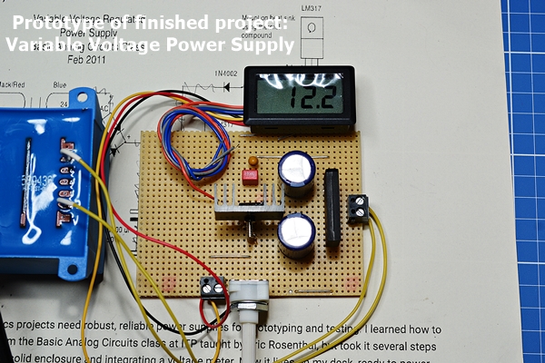
 L’auteur Gust MEES est Formateur andragogique / pédagogique TIC, membre du “Comité Conseil” de “Luxembourg Safer Internet” (LuSI), appelé maintenant BEESECURE, partenaire officiel (consultant) du Ministère de l’éducation au Luxembourg du projet ”MySecureIT“, partenaire officiel du Ministère du Commerce au Luxembourg du projet ”CASES” (Cyberworld Awareness and Security Enhancement Structure). L’auteur était aussi gagnant d’un concours en électronique en 1979 ( Pays germaniques ) et voyait son projet publié dans le magazine électronique “ELO”. L’auteur Gust MEES est Formateur andragogique / pédagogique TIC, membre du “Comité Conseil” de “Luxembourg Safer Internet” (LuSI), appelé maintenant BEESECURE, partenaire officiel (consultant) du Ministère de l’éducation au Luxembourg du projet ”MySecureIT“, partenaire officiel du Ministère du Commerce au Luxembourg du projet ”CASES” (Cyberworld Awareness and Security Enhancement Structure). L’auteur était aussi gagnant d’un concours en électronique en 1979 ( Pays germaniques ) et voyait son projet publié dans le magazine électronique “ELO”.
The author Gust MEES is ICT Course Instructor, ”Member of the Advisory Board” from “Luxembourg Safer Internet” (LuSI), BEESECURE, Official Partner (Consultant) from the Ministry of Education in Luxembourg, project “MySecureIT“, Official Partner from the Ministry of Commerce in Luxembourg, project “CASES” (Cyberworld Awareness and Security Enhancement Structure). The author was also a winner of an electronics contest (Germanic countries) in 1979 and got his project published in the “Electronics Magazine ELO”. |
.
.
Keywords necessary for me to create this blog post: Arduino UNO R3, Arduino NANO, UNO R3 Project, LCD 1602, Sensors, DHT11, DHT22, Temperature/Humidity Sensor, coding, learning to learn, learning by doing, trouble shooting, hygrometer, I2C, LCD 20×4,
.
.
.
.