RSS

Tag Archives: Arduino IDE

Grove Beginner Kit for Arduino | SEEEDSTUDIO | The BREAKOUT | Temperature/Humidity on OLED Display |First Steps with the Arduino-UNO R3 and NANO | Maker, MakerED, Maker Spaces, Coding

Grove Beginner Kit for Arduino | SEEEDSTUDIO | The BREAKOUT | Temperature/Humidity on OLED Display |First Steps with the Arduino-UNO R3 and NANO | Maker, MakerED, Maker Spaces, Coding

.


.


Temperature/Humidity on OLED Display | THE Breakout

In a previous tutorial WE have seen the Grove Beginner Kit for Arduino from SEEEDSTUDIO https://gustmees.wordpress.com/2020/08/03/grove-beginner-kit-for-arduino-seeedstudio-first-steps-with-the-arduino-uno-r3-and-nano-maker-makered-maker-spaces-coding/, now WE make THE BREAKOUT to use the different modules with OWN Code examples.

You can also take the modules out and use Grove cables to connect the modules. To do so, you need a sharp cutter, see PIC, please.

.

.

My recommendation for sharp cutters, which I use as well:

.


.

Once cut out you have made the BREAKOUT and in this case the two modules “OLED Display 0.96 inch” and “Temperature/Humidity” modules are ready to get connected to the main module. NOW we have to connect them through the delivered connection cables. Here below a picture:

.

.

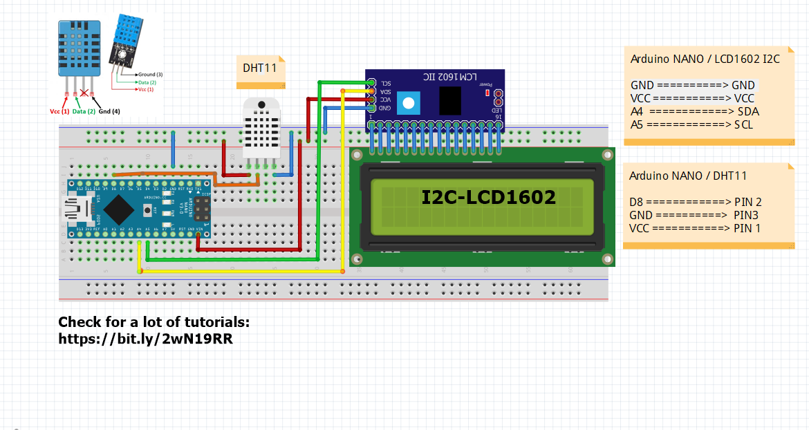
As you can see, the OLED-Module is connected to the I2C connector, while the “Temperature/Humidity-Module” is connected to the “D3” connector. See PIC below, please:

.

.

SO WHY the “D3” connector for the “Temperature/Humidity-Module”?! Well, let us have a look on the code:

.

.

As you can see in this shown part of the code, there is marked ===> “#define DHTPIN 3“, SO it should GET connected to the “D3-connector” on the main board! If you use “D4” or whatever connector, SO you should change the code from “3” to “4” and so on!!! Give it a try and play around with it for understanding 😉

.


Temperature/Humidity on OLED Display | THE Code

Well, the two connections with the provided cables with connectors took ONLY a few seconds, ISN’T it? 😉 Let’s GO now to upload the code. Open your “Arduino IDE“, click on “NEW“, erase the few lines marked in there, make a “Copy&Paste” from the mentioned Code below and paste it in the “Arduino IDE (NEW)” and upload it, here below the code:

.

.

As you can see there is a “special” indication on the display, THE “Heat Index“, WHAT is it?! I encourage you to read my following tutorial which explains:


Have fun learning with PracTICE and stay tuned for next adventures of learning 😉

.


.

L’auteur Gust MEES est Formateur andragogique / pédagogique TIC, membre du “Comité Conseil” de “Luxembourg Safer Internet” (LuSI), appelé maintenant BEESECURE, partenaire officiel (consultant) du Ministère de l’éducation au Luxembourg du projet  ”MySecureIT“, partenaire officiel du Ministère du Commerce au Luxembourg du projet ”CASES” (Cyberworld Awareness and Security Enhancement Structure)..


The author Gust MEES is ICT Course Instructor, ”Member of the Advisory Board” from “Luxembourg Safer Internet” (LuSI), BEESECURE, Official Partner (Consultant) from the Ministry of Education in Luxembourg, project “MySecureIT“, Official Partner from the Ministry of Commerce in Luxembourg, project “CASES” (Cyberworld Awareness and Security Enhancement Structure).

.

.


.

Keywords necessary for me to create this blog post: Arduino UNO R3, Arduino NANO, Grove, Grove Beginner Kit for ARDUINO, Coding, Maker, MakerED, Maker Spaces, OLED, DHT11, Temperature and Humidity Monitor, I2C, SEEDSTUDIO,

.

.


Tags: , , , , , , , , , , , , , , , , , , , , ,

First Steps with the Arduino-UNO R3 and NANO | Maker, MakerED, Coding | I2C LCD Temp./Humidity displaying

First Steps with the Arduino-UNO R3 and NANO | Maker, MakerED, Coding | I2C LCD Temp./Humidity displaying

.

LCD1602 and LCD2004

.


Displaying Temperature/Humidity on a I2C LCD 

We were already playing around, as seen on my tutorials below, with the Temperature/Humidity sensors DHT11, DHT22 and LCD1602, without I2C possibility. There were a lot of cables to connect, we will try out this time to use a LCD with I2C bus connection as it uses ONLY 4 wires to connect. It’s a perfect project for newbies in coding as they will see the measured values directly on the LCD screen, the success and happy factor is guaranteed!

Related tutorials:


Let us have first a look on the wiring (cabling) which is actually very easy, have a look below please:

.

Fritzing-Wiring

====> Click image, please, to enlarge.

The wiring (cabling) will take about +/- 5-10 minutes depending on your own rhythm… Let us have a look on the coding now: we will use exactly the same code (Sketch) as in our first tutorial here, which we will change just a bit to fit for I2C LCD1602 display:

Copy&Paste the code from above tutorial where it is marked “I also made an example where I display the results on a LCD. Here’s the source code of that example:” and paste it into the Arduino IDE. Connect the Arduino NANO with your computer now. Open the Arduino IDE and choose the board “Arduino NANO”, see screenshot below, please:

Arduino-IDE-Board Manager-1

Click image, please, to enlarge.

.

Next step, on the same Arduino IDE select the Processor:

.

Arduino-IDE-Board Manager-OLD-NEW-BOOTLOADER

Click image, please, to enlarge.

.

TIP: when the LED on the Arduino NANO is lightning GREEN it is an original NANO and you must choose “Atmega328P”; if the LED is lightning RED, it is a clone and you must choose “Atmega328P (Old Bootloader)”.

.

NOW it is about time to adapt the code (Sketch) to an I2C-LCD1602 display, let us have a look on the Sketch (the original):

.

OLD Code to change

Click image, please, to enlarge.

.

As we can see in line 10: the library is meant for a normal LCD display, it needs to get changed for a “I2C LCD Library”.

In line 15: the same it shows the wiring pins for a normal LCD display, it needs to get changed for a “I2C LCD” display.

In line19: It is BETTER to add as well the I2C-Address, mostly “0x27” OR “0x3F”.

That is NOT much to change, we will see in the screenshot below the How-To:

.

NEW Code to change

Click image please, to enlarge.

.

By enlarging (click on the image) you will see by comparing where the changes are. I commented in the lines the WHY… Try it out to change it yourselves or just download the Sketch (Code) here below who is working:

Copy&Paste this code into a NEW Sketch on the Arduino IDE and upload now the code to the Arduino NANO (or Arduino UNO) and enjoy it! 😉 Here below a photo of the working sketch:

.

DHT11 on LCD I2C Display

.

And in case of that you have a I2C LCD with 20×4 configuration it works also, check photo below please:

.

I2C LCD2004 and DHT11

.

As you can see the two first lines from 4 possible lines are only used, that is normal as the Sketch (Code) is actually written for a 2 line LCD. BUT we can add some lines of code in the original Sketch to make it working on 4 lines, which is very easy actually, check below please for explication:

.

Printing text on the LCD

Click image, please, to enlarge.

.

As you can see in line 30 in above screenshot of the code ===> “lcd.setCursor(0,0); // Sets the location at which subsequent text written to the LCD will be displayed” the the line is set to “0” which means the first line on the LCD1602. By changing the value to “lcd.setCursor(0,1)” in line 30 and in line 34 to “”lcd.setCursor(0,2)” the text will be displayed as follows, see photo below please:

.

I2C LCD2004 DHT11

.

NOW, as you can see, we have two lines without any text where we could bring in some text. Let us try to find out HOW! We have seen already that “lcd.setCursor(0,0) above. We used in above example the lines 2 and 3 from 4 lines which were displayed as shown in above photo, right?


Printing text on the LCD in 4 lines

Click image, please, to enlarge.

.

Check lines 26 and 27 and also lines 37 and 38: I added them, do the same and the text between the “………” you may change it with your OWN text what will result in following, check photo below, please:

.


I2C LCD2004 4 lines of text

.

BUT wait, my text looks centralized and yours NOT, HOW?! Check photo below, please which explains:

.

4 Lines centered on I2C LCD

.


Prices and where to order


LCD1602 + I2C Modul

LCD1602-I2C

Click image, please, to enlarge.

Arduino NANO

ARDUINO NANO

Click image, please, to enlarge.


LCD2004-I2C

Click image, please, to enlarge.


 Temperature/Humidity Sensors

DHT11

.

.

Stay tuned for next blog post(s) 😉

.


.

GUST-AVRIL2014-800px-2L’auteur Gust MEES est Formateur andragogique / pédagogique TIC, membre du “Comité Conseil” de “Luxembourg Safer Internet” (LuSI), appelé maintenant BEESECURE, partenaire officiel (consultant) du Ministère de l’éducation au Luxembourg du projet  ”MySecureIT“, partenaire officiel du Ministère du Commerce au Luxembourg du projet ”CASES” (Cyberworld Awareness and Security Enhancement Structure). L’auteur était aussi gagnant d’un concours en électronique en 1979 ( Pays germaniques ) et voyait son projet publié dans le magazine électronique “ELO”.


The author Gust MEES is ICT Course Instructor, ”Member of the Advisory Board” from “Luxembourg Safer Internet” (LuSI), BEESECURE, Official Partner (Consultant) from the Ministry of Education in Luxembourg, project “MySecureIT“, Official Partner from the Ministry of Commerce in Luxembourg, project “CASES” (Cyberworld Awareness and Security Enhancement Structure).

The author was also a winner of an electronics contest (Germanic countries) in 1979 and got his project published in the “Electronics Magazine ELO”.

.

.

Keywords necessary for me to create this blog post: Arduino UNO R3, Arduino NANO, UNO R3 Project, LCD 1602, Sensors, DHT11,  DHT22, Temperature/Humidity Sensor, coding, learning to learn, learning by doing, trouble shooting, hygrometer, I2C, LCD 20×4,

.

.

.

.


Tags: , , , , , , , , , , , , , , , , , ,

First Steps with the NodeMCU ESP8266 Wi-Fi Module | Maker, MakerED, Coding | Tips

First Steps with the NodeMCU ESP8266 Wi-Fi Module | Maker, MakerED, Coding | Tips

.

ESP8266-NodeMCU

.


First Steps with the NodeMCU ESP8266 Wi-Fi Module

Click image, please, to enlarge.

In our previous tutorials we were using already the NodeMCU ESP8266 Wi-Fi Module and we discussed about “Security“, “Cyber-Security” issues while using “IoT“, “Internet of Things” and the importance that the router MUST be protected by a NEW password and NOT ALLOW to let connect any devices to our router/internet, unless we decide to let them (ONLY our owns) connect!

Please check again the tutorials below:

It was a bit a difficult procedure to find out the “MAC Address” of the NodeMCU ESP8266 Wi-Fi Module, isn’t it?! Well there is a more easy way to find out with a little Sketch.

Please check the tutorial and copy the Sketch from:

Now it is much more easy to run a project with a NodeMCU ESP8266 Wi-Fi Module. Connect your module to the computer through the USB cable,  chose the board in the Arduino IDE and upload the sketch. Check below the how-to, please.

Click the image, please, to enlarge.

.

Please check again (I don’t want to reinvent the wheel…) the tutorial below who explains very well in detail:

Once having the “MAC Address” of our NodeMCU ESP8266 Wi-Fi Module we can now easily incorporate it into the allowed devices in our router.

.

NOW, click on the button “Add Wireless Device” as shown in above image.

.

Router-4

Click image, please, to enlarge.

.

A new window opens where you can add the new devices “MAC Address” which you wrote down before. Do so please and then click the button “OK“. Go back and have a look if the device is now in the authorized devices in your Network.

SO, now when you use a Sketch with “IoT” with the NodeMCU ESP8266 Wi-Fi Module, the device is recognized and allowed in your Network!

.


.

GUST-AVRIL2014-800px-2L’auteur Gust MEES est Formateur andragogique / pédagogique TIC, membre du “Comité Conseil” de “Luxembourg Safer Internet” (LuSI), appelé maintenant BEESECURE, partenaire officiel (consultant) du Ministère de l’éducation au Luxembourg du projet  ”MySecureIT“, partenaire officiel du Ministère du Commerce au Luxembourg du projet ”CASES” (Cyberworld Awareness and Security Enhancement Structure). L’auteur était aussi gagnant d’un concours en électronique en 1979 ( Pays germaniques ) et voyait son projet publié dans le magazine électronique “ELO”.


The author Gust MEES is ICT Course Instructor, ”Member of the Advisory Board” from “Luxembourg Safer Internet” (LuSI), BEESECURE, Official Partner (Consultant) from the Ministry of Education in Luxembourg, project “MySecureIT“, Official Partner from the Ministry of Commerce in Luxembourg, project “CASES” (Cyberworld Awareness and Security Enhancement Structure).

The author was also a winner of an electronics contest (Germanic countries) in 1979 and got his project published in the “Electronics Magazine ELO”.

.

Stay tuned for next blog post(s) 😉..
.

Keywords necessary for me to create this project: ESP8266, Wi-Fi module, ESP8266 and Adafruit Feather HUZZAH NOT the same pinout!!, where to buy?, Arduino IDE, web server, Coding, Maker, MakerED, MakerSpaces, IoT, Internet of Things, Router, 

.

.

.

.

.

.


Tags: , , , , , , , , , , , , , , , , ,

First Steps with the ESP8266 Wi-Fi Module | Maker, MakerED, Coding | Adafruit Feather Huzzah Weather station

First Steps with the ESP8266 Wi-Fi Module | Maker, MakerED, Coding | Adafruit Feather Huzzah Weather station

.


Weatherstation-Adafruit-Feather-HUZZAH

.


ESP8266 WiFi Weather Station with Color TFT Display

We were playing around already with LED MATRIX’s, devices to visualize measured values and/or texts. In this blog post (Tutorial) we will use a TFT Display (Thin-film-transistor liquid-crystal display) with touch screen to display a three (3) days weather forecast with moon phases. This little weather station acquires its data over a Wi-Fi connection from an online weather server, Wunderground.

We will use devices from ADAFRUIT; they have developed a special product series for easy mounting, the FEATHER series. We need the TFT FeatherWing – 2.4″ 320×240 Touchscreen and the ADAFRUIT Feather HUZZAH which has included an ESP8266. We used the ESP8266 already in our previous blog post <===> First Steps with the ESP8266 Wi-Fi Module | Maker, MakerED, Coding | Scrolling Text (Time, Temp., Humidity…) with 8×8 LED MATRIX  <===> so we are already familiar with its use!

What is GREAT with this project, there ISN’T any wiring, no cables to connect; apart from plugging in the accumulator! 😉 BUT, please check the video below who explains in detail:

.

.


Detailed parts list, supplier and prices

Please find below the detailed parts list as well as the supplier and the prices.


Item and quantity

Supplier and order number

Price

ADAFRUIT Feather HUZZAH ADAFRUIT: ID 3046 18.95$
ADAFRUIT TFT FeatherWing – 2.4″ 320×240 Touchscreen  ADAFRUIT: ID 3315 29.95$ 
 Lithium Ion Battery – 3.7v 2000mAh ADAFRUIT: ID 2011 12.50$
Slide switch  1$
  Total: 62.40 $

..

I suggest to you to read the full article from ADAFRUIT here <===> https://learn.adafruit.com/wifi-weather-station-with-tft-display/overview?embeds=allow  <===> who explains in detail ALL the necessary steps!!

For the case of the weather station ADAFRUIT provides the 3D Design files, so you can 3D print it:

As you can see the price is reasonable for this project, ONLY 62.40$ and easy to realize! ALL what YOU need is a bit time, passion and here we GO! 😉 Have FUN!

Online ordering links:


Preparation: Libraries, code and API Key

There is some preparation needed before we can test our code for the weather station: I suggest that you read and that you follow each step as shown in this tutorial by ADAFRUIT (very important, otherwise it won’t work!!):

It isn’t difficult, but it needs some time and you must be careful to follow each step!

We need ALSO an account on the weather server Wunderground to create our “API” (Application Programming Interface) which we need to implement in our code settings! THIS is also well explained here:

Same procedure as explained already above, follow very carefully each action step by step!

.

Are there some pit falls? 

1ibdy1vf6wghd-n05dgl-attenzionearchitettofr01YES, this could be!

.


The code is running, how it shows up in reality

Well, you haven’t encounter any problem or the problems are solved, this is WHAT you will see appearing on the TFT:

1
Updating Time
2Updating Conditions
3Updating Forecasts 4Updating Astronomy
5Done...  6Wrong settings code

.

As you can see in “Picture 6“, that is what shows up on the first start! Is it the right time which is displayed? Is it the right measure unit which is displayed (°C OR °F)? If SO, it is OK then, if NOT, then we have to look on the code and change some settings!!

Here below the How-To:

Open the Arduino IDE and click on the “Settings.h” tab, check below where and how to change (adapt) the settings to your country and time zone.

.

Weather station-settings

Click the image, please, to enlarge

Once done, save the code and upload it again. You will GET the right data displayed then as shown below:

.

Weatherstation-Adafruit-Feather-HUZZAH

.


.

GUST-AVRIL2014-800px-2L’auteur Gust MEES est Formateur andragogique / pédagogique TIC, membre du “Comité Conseil” de “Luxembourg Safer Internet” (LuSI), appelé maintenant BEESECURE, partenaire officiel (consultant) du Ministère de l’éducation au Luxembourg du projet  ”MySecureIT“, partenaire officiel du Ministère du Commerce au Luxembourg du projet ”CASES” (Cyberworld Awareness and Security Enhancement Structure). L’auteur était aussi gagnant d’un concours en électronique en 1979 ( Pays germaniques ) et voyait son projet publié dans le magazine électronique “ELO”.


The author Gust MEES is ICT Course Instructor, ”Member of the Advisory Board” from “Luxembourg Safer Internet” (LuSI), BEESECURE, Official Partner (Consultant) from the Ministry of Education in Luxembourg, project “MySecureIT“, Official Partner from the Ministry of Commerce in Luxembourg, project “CASES” (Cyberworld Awareness and Security Enhancement Structure).

The author was also a winner of an electronics contest (Germanic countries) in 1979 and got his project published in the “Electronics Magazine ELO”.

.

Stay tuned for next blog post(s) 😉..
.

Keywords necessary for me to create this project: Adafruit Feather HUZZAH, ESP8266, Adafruit Feather TFT Display, 3 days weather station, weather forecast, moon phases, Wunderground, Wi-Fi module, ESP8266 and Adafruit Feather HUZZAH NOT the same pinout!!, where to buy?, time zone, metric, imperial, °C, °F, Arduino IDE, web server, weather server, 

.

.

.

.

.


Tags: , , , , , , , , , , , , , , , , , , , , , , , , , , , , , , , , ,

First Steps with the Arduino-UNO R3 | Maker, MakerED, Coding | 1.8 Inch TFT with DS3231 RTC and Arduino

First Steps with the Arduino-UNO R3 | Maker, MakerED, Coding | 1.8 Inch TFT with DS3231 RTC and Arduino

.


Correct data displayed and enhanced displaying

.


1.8 Inch TFT with DS3231 RTC and Arduino

We were already playing around with LED MATRIX for time and temperature display with a Wi-Fi connection on an ESP8266, but we didn’t create yet a project with an RTC (Real Time Clock) module and an 1.8 inch TFT display; here we go. We will use again a ready to go code, but we will change it a bit for better looking. SO, we will learn How-To code rectangles and lines for a TFT screen, very easy… It is GOOD to try out different components to get used with coding, Maker, MakerED… Especially when we use displays, which ever ones, as one sees directly the results; sensation of direct success!!

The tutorial in the video shows an Arduino UNO, but we will use in this tutorial an Arduino NANO as it is less expensive (+/- 1/3 of the price of an Arduino UNO) and also it takes less place when integrating the components into a box.

Below you see how to connect the TFT-Display to the Arduino.

.


WIRING-1.8 inch TFT ST7735 on ARDUINO

Click image, please, to enlarge.

.

Check the video below, please:

.

.


Detailed parts list, supplier and prices

Please find below the detailed parts list as well as the supplier and the prices.


Item and quantity

Supplier and order number

Price

1x 1.8 inch Touchscreen  AMAZON (DE): AZDelivery 1,8 Zoll SPI TFT-Display mit 128 x 160 Pixeln für Arduino und Raspberry Pi inkl gratis eBook 9,99€
1x RTC DS3231 AMAZON (DE): AZDelivery Real Time Clock RTC DS3231 und gratis Batterie inklusive I2C für Arduino und Raspberry Pi sowie GRATIS eBook (3x Real Time Clock) 14,99€ / 3 pces 5€
1x Arduino NANO AMAZON (DE): AZDelivery Nano V3.0 CH340 Chip fertig verlötete, verbesserte Version mit USB Kabel, 100 % Arduino Nano V3 kompatibel 7,99€
  Total: 22,98€

.

As you can see it is a very cheap project, ONLY 22,98 € and easy to realize! ALL what YOU need is a bit time, passion and here we GO! 😉 Have FUN! I order my stuff on AMAZON.DE, but you can chose any other supplier as the parts are very popular…

Please follow the whole tutorial with connections (Wiring Diagram) and Code (Sketch) here:

When copying the code on the mentioned website <===>   http://educ8s.tv/arduino-real-time-clock/  <===> you must be aware of some TYPOS in it!!! Check below please where they are and how to correct them. Once corrected save the code in the Arduino IDE  and upload it. Here are the errors, check below please.

.

Bug in sketch-1

.

As you can see above the “Arduino IDE” shows an error and highlighted it in Line 1. The sign “<” is too much, delete it and save your sketch, then upload it again to the Arduino NANO. You might get a second error message again, check below please.

.

Bug in sketch-2

.

In above image you will see a new error message in Line 100. Check below please on how-to correct it.

.

Bug in sketch-3-correction

.

Same procedure as above, save it in the Arduino IDE and upload it again to the Arduino NANO (UNO). Here what will show up now.

.

Working sample without drawn rectangle

.

There are some problems with the time and day still… I didn’t follow step-by-step instructions on the video, OK let’s have a look in deep now!! Please check the video tutorial @ 03:15 for the settings and follow them strictly, otherwise your clock setting will NOT working!! Done so, it will be working great. I did some more changes in the coding such as changing the text colors and ALSO to draw a rectangle and some lines to make it look BETTER, please check below.

.

Draw Rectangle

.

As you can see, I added some new code snippet from lines 142 to 151, this will draw a rectangle around the TFT screen and it will draw white lines under the measured values. It will look BETTER, well that’s what I think and my wife as well; you just do the way as you want, up to you 😉 Here below the result…

.

Correct data displayed and enhanced displaying

.

.

Here below the version with the Arduino NANO.

.

DS3231 and 1.8 TFT on Arduino NANO

.

SO, that’s it folks, enjoy it and have fun 😉

.


GUST-AVRIL2014-800px-2L’auteur Gust MEES est Formateur andragogique / pédagogique TIC, membre du “Comité Conseil” de “Luxembourg Safer Internet” (LuSI), appelé maintenant BEESECURE, partenaire officiel (consultant) du Ministère de l’éducation au Luxembourg du projet  ”MySecureIT“, partenaire officiel du Ministère du Commerce au Luxembourg du projet ”CASES” (Cyberworld Awareness and Security Enhancement Structure). L’auteur était aussi gagnant d’un concours en électronique en 1979 ( Pays germaniques ) et voyait son projet publié dans le magazine électronique “ELO”.


The author Gust MEES is ICT Course Instructor, ”Member of the Advisory Board” from “Luxembourg Safer Internet” (LuSI), BEESECURE, Official Partner (Consultant) from the Ministry of Education in Luxembourg, project “MySecureIT“, Official Partner from the Ministry of Commerce in Luxembourg, project “CASES” (Cyberworld Awareness and Security Enhancement Structure).

The author was also a winner of an electronics contest (Germanic countries) in 1979 and got his project published in the “Electronics Magazine ELO”.

.

Stay tuned for next blog post(s) 😉..
.

Keywords necessary for me to create this blog post: Arduino UNO R3, Arduino NANO, TFT DISPLAY, Coding, Maker, MakerED, MakerSpaces, #RTC, Real Time Clock, Temperature, DS3231,…

.

.

.


Tags: , , , , , , , , , , , , , , , , , , , , , ,